Flexible Thin Film Pressure Sensor S14-G
Ultra Thin
Power Saver

Swift Response Rate
Wide Detection Range

High Sensitivity
Easy Integration
The S14-G sensor, a remarkable thin film pressure sensor with a thickness of only 0.25mm. Built to withstand rigorous usage, this compact yet robust sensor is equipped with a range of powerful functionalities, empowering you to deliver exceptional handwriting interpretation.
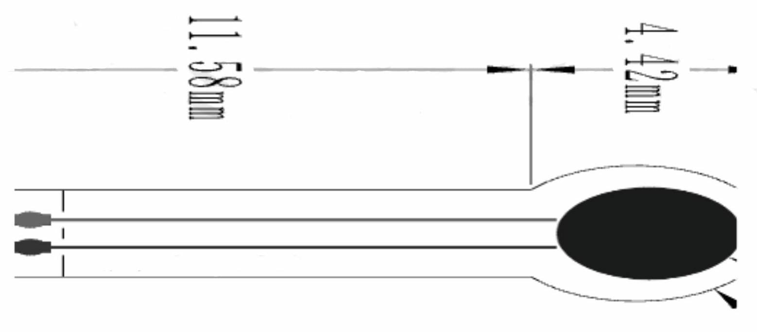
| Product Dimensions | |
| Length | 16 mm |
| Width | 5 mm |
| Sensitive Area | 3.4 |
| Pin Pitch | 1.0 |
| Tolerance | 0.2 |
| Product Performance | |
| Measuring Range | 0-500 g |
| Thickness | <0.25 mm |
| Response Point 1 | <30 g |
| Repeatability | +10% (50% load) |
| Consistency Note 2 | +20% |
| Hysteresis | +10% (RF+ – RF-)/RF+ |
| Durability | >1 million times |
| Initial Resistance | >10M2 (no load) |
| Response Time | <1 millisecond |
| Recovery Time | <15 milliseconds |
| Test Voltage | Typical Value DC 3.3V |
| Operating Temperature | -20°C – 60°C |
| Electromagnetic Interference | Not Generated |
| Electrostatic Discharge | Not Sensitive |
Notes:
- The response point is when the pressure gradually increases from 0, causing the sensor’s resistance to decrease below 1MΩ, initiating a “response.” By calibrating with a program algorithm, the consistency error between devices can be reduced to within ±15%, ensuring improved uniformity, accuracy, performance, and reliability.
Instruction for Use:
When using the S14-G flexible pressure sensor, it is important to follow these guidelines for optimal performance:
- Place the pressure-sensitive zone of the sensor on a firm, flat surface. Avoid using it on curved or irregular surfaces, as this can cause the sensor to be conductive even without pressure, affecting its response.
- When using the sensor on rigid and hard surfaces where the contact area exceeds the sensitive area, it may result in a small and unstable pressure response. To mitigate this, we recommend attaching a round soft rubber pad to the center of the sensitive area. The pad should have a diameter slightly smaller than the sensitive area, and its surface area should be at least 60% of the sensitive area. This ensures optimal performance and stability during pressure measurements.
- Use double-sided tape to securely fix the sensor on the supporting surface. Ensure that the surface is clean and tidy before applying the tape. We recommend using 3M brand double-sided tape, which provides reliable adhesion.
- Once pressure is applied to the sensor and held, there may be a slight drift in the output resistance value over time, usually within a 5% range. To minimize this error, timing calibration is recommended. During calibration, it is important to match the waiting time after applying pressure with the waiting time in actual applications.
Since the force state of the sensor can vary in different scenarios, we advise users to arrange the sensor according to their specific application needs. Conducting drift parameter testing tailored to their use case will help optimize the sensor’s performance and ensure accurate measurements.
By following these guidelines, you can ensure optimal performance and accuracy when using the SG14-G flexible pressure sensor.
Flexible Thin Film Pressure Sensor S14-G
Take notes in the most sophisticated way with the S14-G!
This flexible film pressure sensor is an innovative solution tailored specifically for electronic pens. This cutting-edge sensor is primarily designed for pressure triggering and detection of handwriting gestures, enabling precise and accurate measurement of writing pressure.
With the S14-G sensor, you can effortlessly detect even the subtlest changes in writing pressure, resulting in a more responsive and natural writing experience. Whether you’re an artist looking to capture delicate brush strokes or a student taking notes, this sensor ensures that your writing is captured with exceptional precision.
But that’s not all! the S14-G sensor goes beyond pressure detection. It boasts advanced handwriting recognition capabilities, allowing it to analyze the pressure patterns during writing and recognize different handwriting styles and characters. This feature streamlines data input, making it easier and more efficient.
In addition, the S14-G sensor offers an innovative posture correction functionality. By monitoring the pressure applied during writing, it provides real-time feedback on your posture, helping you maintain a healthier writing position and reducing the risk of strain or discomfort.
The S14-G flexible film pressure sensor seamlessly integrates into various digital pen models, thanks to its flexible nature. It effortlessly conforms to the unique shapes and sizes of different pens, ensuring optimal performance and compatibility.
Experience the future of electronic pens with the S14-G flexible film pressure sensor. Elevate your writing experience with its exceptional pressure detection, handwriting recognition, and posture correction capabilities. Unlock new possibilities and unleash your creativity with the S14-G sensor
The S14-G pressure sensor utilizes the partial pressure method for measurement. It is connected in series with resistor R1, with both ends connected to VCC and GND, forming a basic voltage dividing circuit. The voltage obtained from the division is then connected to Vout.
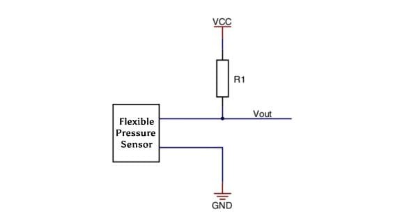
The change in the sensor’s output resistance, corresponding to the change in pressure, can be converted into a voltage change signal. To meet specific application requirements, an appropriate load resistor R1 should be selected. Typically, a range of 1kΩ to 100kΩ is recommended, with the load resistance ideally being 50% of the pressure range’s corresponding resistance value.
Vout is connected to the ADC interface of the microcontroller, enabling voltage detection. Additionally, it can be connected to the external interrupt IO port of the MCU, allowing for the utilization of the pressure trigger function.
